THE SME TEAM IS CURRENTLY TRAVELLING IN INDIA
Hover to zoom
BST Trolleys
HIGH POWERED WORKSHOP TROLLEY
Ref no. BST
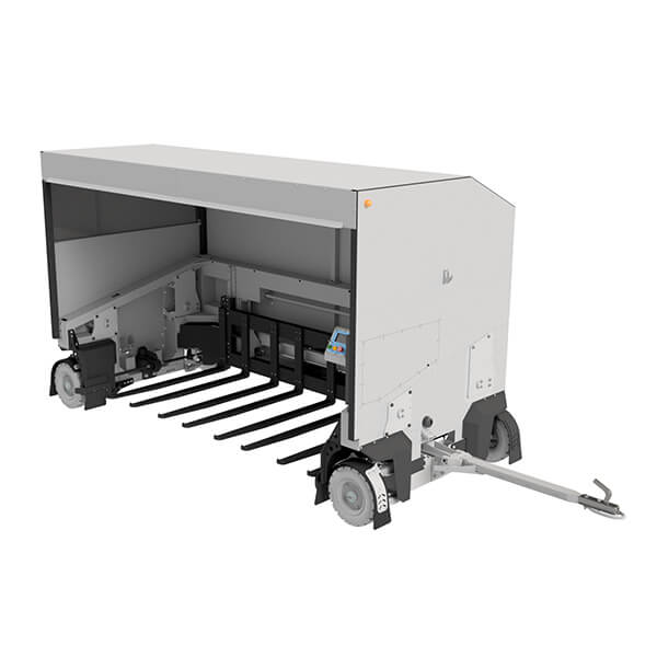
This workshop trolley is designed to transport spare parts around a workshop. The trolley is equipped with a four-wheel steering system which allows the rear wheels to follow the path of the front wheels with minimum deviation when making a 90° turn. Multiple trolleys can be connected to a tow motor to transport a large quantity of spare parts on a single trip.
Each trolley is capable to lift a total of 1000kg. The LCD screen incorporated into the control panel, displays important information such as the weight of the load lifted, the overall distance travelled as well as the total number of lifts which the trolley has done. The LCD will also display an error when there is an issue which needs attention. Alternative communication is done via Bluetooth to smartphones. This communication enables the operator to run a diagnostic test which reduces downtime due to fault finding.
Specifications
Login to Access comprehensive content
Login to Access comprehensive content

Specifications
|
Reference No: BST |
|
| Load Capacity | 1000kg |
| Power Supply | 80V DC |
| Motor Power | 3kW |
| Motor Torque | 10N⋅m |
| Motor Speed | 3000rpm |
|
Fault Finding |
Bluetooth/HMI |
| Power Requirement (Under Maximum Operating Conditions) | 50A @ 80VDC |
PDF Download
SUSPENSION AND STEERING INFORMATION
Each wheel on the trolley is fitted with two control arms. A ball joint and wheel stub shaft are bolted to each control arm. These ball joints provide the wheel with the necessary degrees of freedom.
The shock absorber (together with a spring) is fitted onto the control arm assembly and trolley body, making up a double wishbone suspension system. Onto the wheel stub shaft, a link is welded for the tie rod end whereto a rack end is bolted. The steering link completes this assembly between the two wheels. The tow bar interfaces with the steering link to enable the trolley to turn. This trolley is equipped with a four-wheel steering system, which is obtained by means of a mechanical link between the front and rear wheels.
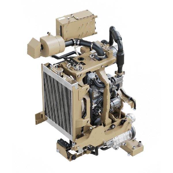
LIFTING INFORMATION
The lifting of the forks is done by means of single motor and gearbox, and is capable of lifting 1000kg in total. The gearbox is fitted with a double output shaft and the main drive shafts are connected to bevel gearboxes which transfer the rotational movements by 90 degrees.
A ball screw is then attached to each bevel gearbox for lifting the lifting frame. The ball screw is supported in a fixed and floating bearing housing each fitted with a grease nipple for maintenance purposes. The lifting frame is guided with a linear bearing system, and each linear is also fitted with a grease nipple. The lifting interval (bottom to top and vice versa) is < 8 seconds.
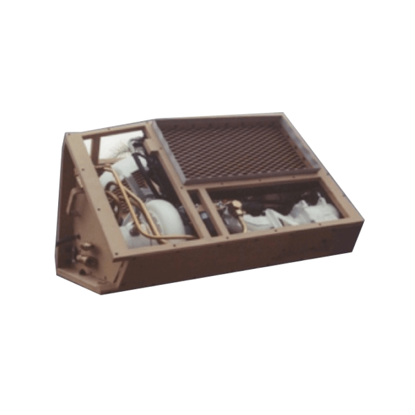
ELECTRIC AND ELECTRONIC INFORMATION
The motor is equipped with its own controller. SME uses a PLC to interface control inputs, sensors and motorised movement.
Upper and lower limit switches detect and stop movement of the lifting forks.
The power requirement for each trolley under maximum operating conditions is 50A for 80VDC.